


IO_Link definition
IO-Link is an innovative point-to-point communication interface for sensor/actuator applications that comply with IEC 61131-9 standards.
IO-Link contains the following system components:
1. IO-Link master station.
2. IO-Link devices, such as: Sensor/actuator, RFID reader, I/O module, Valve
3.Wire or 5-wire unshielded standard cable: An engineering configuration tool for configuring and assigning parameters to IO-Link.
Benefits of IO_Link
The IO-Link system, if used as a digital interface when connecting sensors/actuators, has the following significant advantages:
● Comply with the open standard of IEC 61131-9
- Devices are integrated in all traditional fieldbus systems and automation systems in the same way.
● Use a tool to complete parameter setting and unified data management
- Fast configuration and debugging
-- Easily create the latest factory documentation (including sensors/actuators)
● The sensor/actuator adopts simple and unified wiring mode, and the interface used is very few
- Sensor and actuator adopt a unified standard interface, independent of their own complexity (switching signal, measurement signal, multi-channel signal, binary signal, mixed signal, etc.)
- The types and inventory used decreased significantly
- Fast debugging
- The IO-Link device can be combined with the sensor/actuator without IO-Link on the IO-Link master station
● Continuous communication between the sensor/actuator and the CPU
- Access all process data, diagnostic data, and device information
- Access device-specific data, such as energy data
- Remote diagnosis can be performed
● Continuous diagnostic data can be transmitted down to the sensor/actuator level
- The troubleshooting workload is greatly reduced
- The fault risk is minimized
- Adopt preventive maintenance and optimize service and maintenance planning
● Dynamic change of sensor/actuator parameters via controller or HMI operator
- Downtime during product replacement is significantly reduced
- Significantly improved the diversity of devices
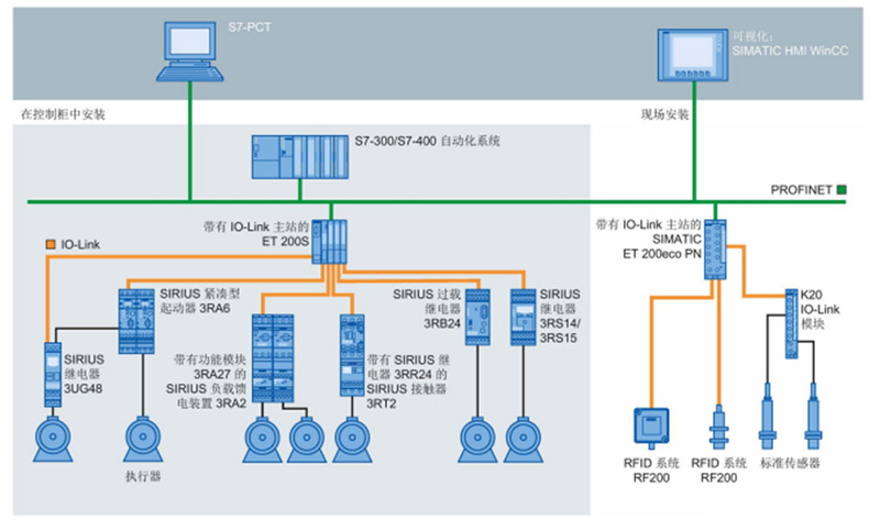
IO-Link system
The IO-Link master station establishes a connection between the IO-Link device and the automation system. When the IO-Link master station is used as a component of the I/O system, it can be installed either in the control cabinet or directly on site as a remote I/O with IP65/67 protection.
The IO-Link master station communicates data via a variety of fieldbuses or product-specific backplanes. IO-Link master station can be equipped with multiple IO-Link ports (channels). IO-Link devices can connect to various ports (point-to-point communication).
IO_Link protocol
IO_Link is a point-to-point serial digital communication protocol. Its purpose is to periodically exchange data between sensor actuators (PLCS).
IO-Link master station transfers data between the IO_Link device and the PLC. It is usually a distributed IO mode with an IO_Link connection channel on the module. The IO_Link device is connected to the channel of the IO_Link master station through cables, and the IO_Link master station exchanges data with the PLC through the bus.
Each IO-Link device is connected to a channel of the IO-Link master station, so IO-Link is a point-to-point communication protocol rather than a bus protocol.
IO_Link interface
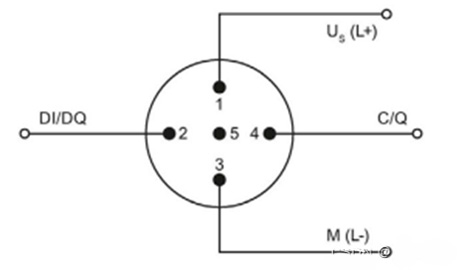
IO-Link devices come in sensor and actuator types: the sensor has a 4-pin connector and the actuator has a 5-pin connector. IO-Link master stations usually come with a 5-pin M12 socket.
Pin assignment in accordance with IEC 60974-5-2 is specified as follows:
Pin 1:24V
Pin 3:0V
Pin 4: Conversion or communication cable (C/Q)
In addition to the IO Link communication, these three pins also connect to the device power supply.
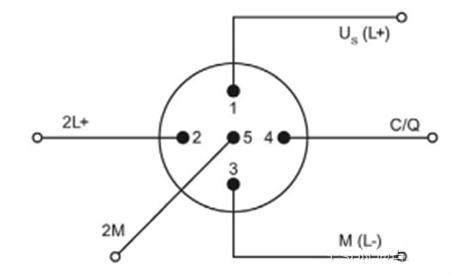
Two types of ports are provided in the IO-Link master specification:
(I) Class A port (Type A) For this type, the function of pins 2 and 5 is not assigned. This function is defined by the manufacturer. Typically, pin 2 is assigned an additional digit channel.
Ii) Class B Port (Type B) This type provides additional power supply voltage and is suitable for connecting devices with high power requirements. At this point, pins 2 and 5 connect the additional (electrically isolated) supply voltage, which is connected through a 5-wire standard cable.
IO_Link Cable connection
The device is connected to the main station by a 3-wire or 5-wire unshielded standard cable (up to 20 m), through which the sensor is connected. There is no need to shield or comply with special regulations when installing cables.
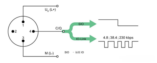
IO_Link Working mode
The master IO-Link port works in the following modes:
IO-Link:
This port is used for IO-Link data communication.
DI:
This port will be used as a numeric quantity input.
DQ:
The port will be output as a numeric quantity.
PROFINET
PROFINET is an open, standard, real-time industrial Ethernet standard.
The goals of PROFINET are to:
● Establish open automation Ethernet standard based on industrial Ethernet
Although industrial Ethernet and standard Ethernet components can be used together, industrial Ethernet devices are more stable and reliable, and therefore better suited to industrial environments (temperature, anti-interference, etc.).
● Use TCP/IP and IT standards
● To achieve real-time requirements of automation applications
● Fully integrated fieldbus system
Field bus IO_Link module
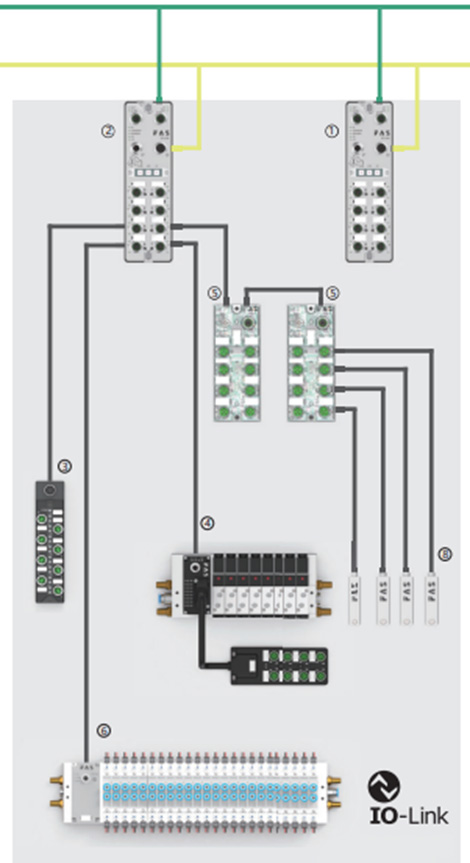
Main station
Industrial Ethernet
Supports multi-protocol communication and is suitable for Profnet, Ethernet/IP, EtherCAT and CC-Link IEF Basic Settings via DIP switch.
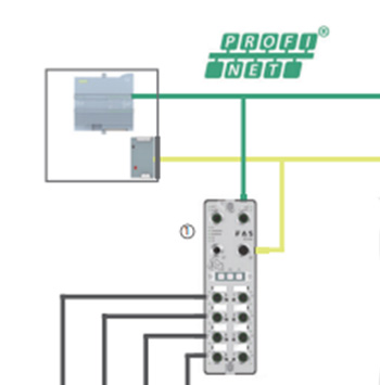
The host station can communicate with PLC over multiple protocols. Profnet communication is used in the diagram. The communication distance is within 100 m.
type
The value includes the IO_Link interface, DI interface, and DO interface. You can configure the number of interfaces based on the required sensor.
Input sensor type, PNP, NPN.
Maximum load current
The maximum load current determines the number of sensors to be connected.
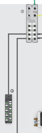
substation
The substation connects to the IO_Link interface of the master station.
IO_Link communication is adopted between the sub-station and the main station, and the communication distance is not more than 20 meters.
Input/output
The input and output quantity can be configured based on actual conditions.
IO_Link port
The child station contains the IO_Link port.
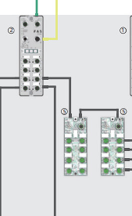
Expansion module
The expansion module can continue to expand the substation.
Analog adapter
Convert an analog signal to an IO_Link signal.
Other fieldbus modules (excluding IO_Link protocol)
type
Only DI and DO are available
connection
PROFNET protocol is used to connect modules to PLC, IO_Link master module, and identical modules. Communication is within 100 meters.
This module has no substations and is directly connected to DI and DO sensors.